Embedded, FPGA & Board-Level Systems
A curated hardware portfolio spanning a two-layer Arduino-Mega-class board, direct-register 40 kHz ADC sampling, a hand-built IR link, FPGA protocols, and CMOS design exercises.
- Build enough low-level fluency to reason about sensing, timing, protocols, power, and hardware interfaces without treating the robot as a black box.
- Curated embedded / digital / PCB project collection
- Robot learning systems still fail at clocks, registers, connectors, signal paths, and power rails; this work makes those layers inspectable.
Who did what
- Individual coursework and project collection — firmware, HDL, PCB layout, tests, and documentation
- Primarily individual undergraduate course and independent projects.
- Arduino Mega reference architecture, ATmega2560 documentation, Vivado, and standard CMOS / digital-design references.
Overview
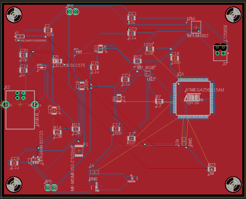
These projects provide the hardware foundation beneath the robotics work. The strongest examples are a two-layer Arduino-Mega-class PCB design with exported Gerbers, a bare-metal ADC sampler configured for 40 kHz acquisition, a custom IR link-layer protocol, timer-interrupt audio projects, FPGA modules and protocol exercises, and transistor-level CMOS design coursework. The board is documented as designed and Gerber-ready, not fabricated; the self-balancing folder contains component validation rather than a complete balancing controller.
Methodology
- Moved from transistor and logic exercises through FPGA simulation and synthesis, direct-register microcontroller work, protocol implementation, and a two-layer board layout.
- Separated schematic/layout completion, manufacturing-file export, fabrication, assembly, and bring-up as different hardware milestones.
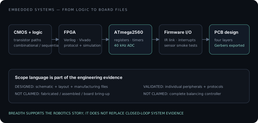
The portfolio moves from transistor and logic design to FPGA modules, microcontroller peripherals, communication protocols, and a complete board layout — emphasizing explicit timing and interfaces at every level.
- CMOS + digital logic
- FPGA modules
- ATmega2560 peripherals
- Firmware protocols + timing
- Two-layer PCB + Gerbers
My contribution
- Designed and exported manufacturing files for a two-layer Arduino-Mega-class board based on the reference architecture with documented personal changes.
- Configured ATmega2560 registers for 40 kHz ADC sampling and implemented interrupt-driven data handling.
- Built an IR protocol and timer-interrupt music projects that make timing and state explicit at the firmware level.
- Implemented FPGA and digital-design exercises in Verilog with simulation and synthesis workflows.
- Used component smoke tests to validate motors, encoders, and inertial sensors without claiming a complete self-balancing robot.
Provenance & claim boundary
- The custom board mirrors the Arduino Mega reference architecture with personal changes; it is not presented as a novel microcontroller platform.
- Gerbers and design files exist, but fabrication is not claimed. Component-validation code is not presented as a finished balancing controller.
Experimental design
- Used simulation, register-level timing checks, peripheral smoke tests, synthesis results, and design-rule outputs appropriate to each artifact.
- No fabricated-board validation is presented because no preserved bring-up record exists.
Results & evidence
Evidence
Board design
attachedTwo-layer schematic/layout and production Gerbers; fabrication not claimed.
Bare-metal timing
attachedDirect-register ADC configuration for 40 kHz sampling.
Protocol implementation
attachedHand-built IR link layer and interrupt-driven projects.
Scope boundary
attachedComponent validation is labeled separately from a complete closed-loop robot.
Metrics
40 kHz
4
ATmega2560
Not claimed
Failure analysis
- Timing, protocol state, sensor wiring, and power interfaces exposed failure modes that high-level frameworks normally hide.
- Several folders stop at component validation, so they cannot support claims about a complete closed-loop robot.
Limitations
- The repository packages work from multiple courses and dates; public upload dates are not project dates.
- The custom board has manufacturing files but no preserved fabricated-board bring-up record.
- Some folders are peripheral validation exercises, not complete embedded products.
Lessons & tradeoffs
- Precise scope language matters in hardware: designed, fabricated, assembled, and validated are different milestones.
- Direct-register work builds intuition for the timing and bandwidth constraints hidden by high-level robotics frameworks.
- Breadth is most useful when tied back to concrete robot interfaces rather than presented as a catalog.
Next questions
- Which board-level design should be fabricated and instrumented for a complete bring-up record?
- How can the low-level timing and sensing work be connected to a repeatable closed-loop robotics experiment?