CLiDA LiDAR Debris Analysis
A five-person sensing project that estimated object dimensions, principal axis, motion, and rotation rate from point-cloud sequences — with final 1 RPM and 3 RPM trials reported against a controlled test stand.
- Estimate the size, orientation, motion state, and rotation rate of a small object from sparse point-cloud sequences.
- Team sensing prototype + controlled experiment + standalone methods package
- It connects algorithm implementation to a physical test stand, ground-truth rates, repeated trials, and a documented team role.
Who did what
- Algorithm developer — LiDAR processing, motion/axis/dimension methods, test hardware support, and report sections
- Five-person CE315 design team with shared hardware, software, testing, and documentation responsibilities.
- LiDAR hardware, NumPy, Open3D, PCA, and ICP methods.
Overview
The Camera LiDAR Debris Analyzer (CLiDA) was a five-person computer engineering design project for characterizing small rotating objects. As algorithm developer, I contributed LiDAR preprocessing, file conversion, dimension measurement, principal-axis estimation, motion detection, and rotation-rate logic, then helped document the verification plan and results. The final team report records ten trials at each of two target rates: 1.009 RPM mean for the 1.0 RPM condition and 3.004 RPM mean for the 3.0 RPM condition, with all 20 trials within ±0.2 RPM. A later public Python package presents the point-cloud methods in a compact, inspectable form using NumPy and Open3D.
Methodology
- Cleaned sequential point clouds, measured axis-aligned dimensions, estimated principal orientation with PCA, gated motion from displacement, and recovered inter-frame rotation with ICP.
- Used 3D-printed silhouettes and mounts to make the sensing geometry and alignment repeatable enough for controlled trials.
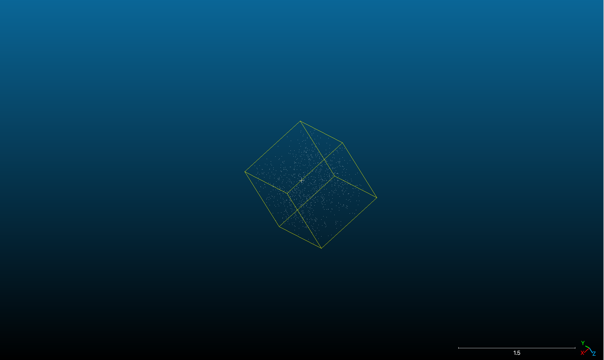
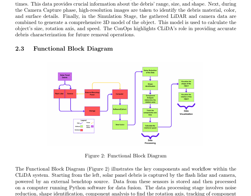
Point-cloud frames are cleaned, measured with bounding boxes, summarized with PCA, screened by a displacement gate, and registered with ICP. A controlled motorized stand supplies repeated target-rate trials for comparison.
- LiDAR point-cloud sequence
- NaN / outlier cleanup
- AABB dimensions + PCA axis
- Motion gate + ICP registration
- RPM estimate vs. test-stand truth
My contribution
- Developed and debugged LiDAR processing for RPM detection, axis identification, dimension measurement, point pruning, and file-format conversion.
- Used PCA to estimate principal orientation and ICP-derived inter-frame rotation for speed and axis estimates.
- 3D-printed silhouettes and mounts to improve repeatable sensor alignment and test geometry.
- Authored manufacturing, verification, risk, planning, and lessons-learned sections of the final report.
- Later packaged the point-cloud methods with sample data, scripts, documentation, and synthetic-cloud tests.
Provenance & claim boundary
- CLiDA was a five-person team project; project management, hardware, software leadership, and test execution were shared across named roles.
- The final team report is the authority for the 20-trial RPM results. The public code package is supporting algorithm evidence, and its included 0.83 RPM sample output is not presented as the final experiment.
Experimental design
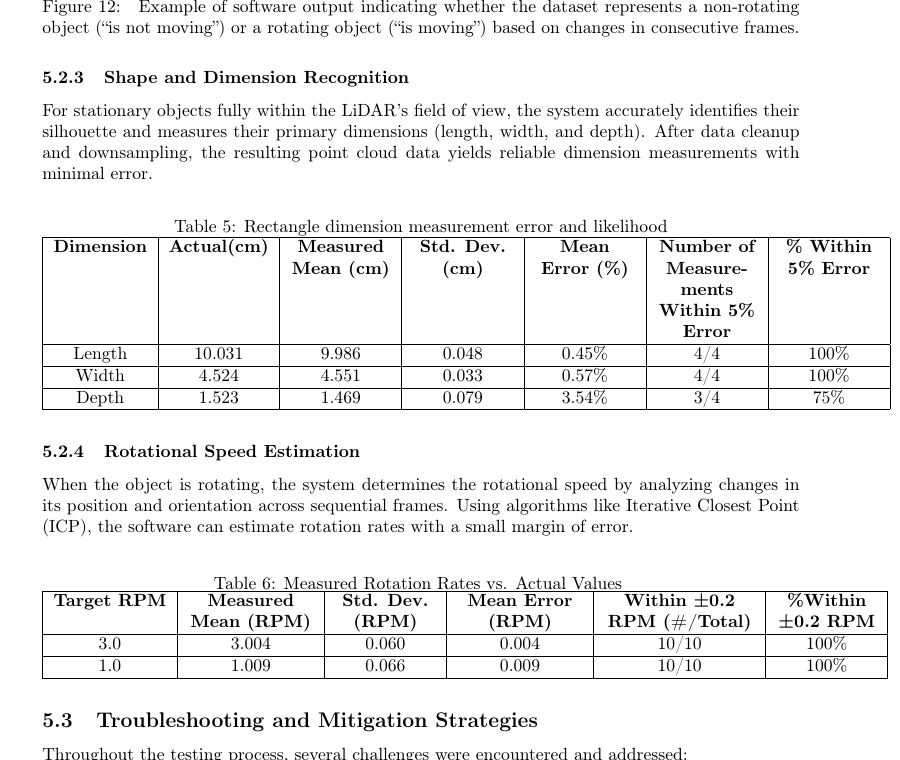
- Compared estimated rotation rate against a motorized test stand at two known conditions: ten trials at 1 RPM and ten trials at 3 RPM.
- Used the final five-person team report as the authority for the protocol, role allocation, and aggregate results; the later public package is supporting method evidence.
Results & evidence
Evidence
Final team report
attachedNames team roles, experimental protocol, individual contributions, and 20 final rotation-rate trials.
Public method package
attachedPreprocessing, dimensions, PCA orientation, motion gate, ICP speed estimation, sample data, and tests.
Hardware setup
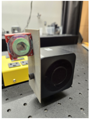
attachedControlled rotating target, known rates, LiDAR mounting, 3D-printed fixtures, and repeated trials.
Result table
attachedTen trials at 1 RPM and ten at 3 RPM; every reported trial was within ±0.2 RPM.
Metrics
1.009 RPM
3.004 RPM
20 / 20
5 people
Failure analysis
- Point-cloud sparsity, surface finish, alignment, overlap, and ICP initialization can dominate the apparent algorithm quality.
- Axis-aligned dimensions vary with orientation, PCA has a sign ambiguity, and the controlled stand does not reproduce unconstrained debris motion.
Limitations
- The experiment used controlled objects and a fixed test stand, not unconstrained orbital debris or a flight-ready sensor system.
- Axis-aligned dimensions are sensitive to object orientation; PCA has a sign ambiguity; ICP depends on overlap and initialization.
- The public package is a compact methods artifact and does not contain the full team report or raw final-trial dataset.
Lessons & tradeoffs
- A clean algorithm is not enough; mounts, surface finish, alignment, and ground truth determine whether its output is meaningful.
- Team reports are useful provenance when they name individual contributions instead of retroactively assigning sole ownership.
- A small public methods package can make a long team report inspectable without pretending the package is the whole project.
Next questions
- How do the estimators behave under tumbling, partial occlusion, and changing sensor range?
- What ground-truth and calibration procedure would be required for unconstrained 3D rotation rather than a fixed-axis test stand?